/ HighTech / Atomic Force Microscope
-
-
MFP-Asylum-NI
The MFP Instrumented NanoIndenter
Producto Descontinuado u obsoleto
|
|
|
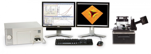
Asylum’s MFP NanoIndenter is a true instrumented indenter and is the first AFM-based indenter that does not use cantilevers as part of the indenting mechanism. These characteristics and the use of state-of-the-art AFM sensors provide substantial advantages in accuracy, precision and sensitivity over other nanoindenting systems.
|
||||||||||||||||||||||||||||||||||||||||||||||||
|
|
||||||||||||||||||||||||||||||||||||||||||||||||
|
Overview and Advantages Unlike cantilever indenters, the MFP NanoIndenter (Figure 1) moves the indenting tip perpendicular to the surface. This vertical motion avoids the lateral movement and errors that are inherent in cantilever-based systems. Compared to conventional commercially-available instrumented nanoindenters, the MFP NanoIndenter provides lower detection limits and higher resolution measurements of force and indentation depth with the superior precision of AFM sensing technology. The indenter is completely integrated with the AFM, providing the unique ability to quantify contact areas by performing AFM metrology of both the indenting tip and the resulting indentation (Figure 2). These direct measurements enable analysis of material properties with unprecedented accuracy relative to indirect calculation methods. The design uses passive actuation through a monolithic flexure, minimizing drift and other errors in depth measurement. The positioning accuracy in the sample plane is subnanometer using the MFP’s closed loop nanopositioning sensors. The NanoIndenter Head utilizes advanced diffraction-limited optics coupled with CCD image capture for precision navigation of the tip to areas of interest on the sample. The integrated software provides a full complement of experimental control and analysis functions, including standard analysis method templates. The system kit includes a set of nanoindenting tips, three different sample mounts, two calibration standards for sensitivity and spring constant verification, as well as the tools and accessories necessary to perform indenting experiments on a full range of materials. This highly quantitative tool, combined with high-end AFM capabilities, breaks new ground in the characterization of diverse materials including thin films, coatings, polymers, biomaterials, and many others. The MFP NanoIndenter Module is available in standard (spring constant typ. 4,000N/m) and low force (spring constant typ. 800N/m) versions exclusively for the
Innovative, Robust Design At the heart of the NanoIndenter is our exclusive sensored closed loop head, designed with a robust flexured transducer for quantitative measurements. Monolithic Design Eliminates Drift and Errors in Depth Measurements Nanopositioning for Accuracy and Precision Diffraction-limited Optics Provide High Resolution Viewing of Tip and Sample Different regions of the sample can be viewed with the optic's independent translation stage. The design allows for easy exchange of objectives to accommodate different sample requirements. A built-in iris diaphragm provides adjustable depth of field and the camera allows for adjustment of exposure time, gain, frame rate, saturation, and gamma. Easy-to-use Pre-calibrated Setup and Calibration Verification Push and Turn Adjustments Maintain Calibration
Direct Measurement for Tip Characterization and Accurate Results Tip characterization is extremely important for quantitative analysis in nanoindenting applications. Conventional nanoindenters must use indirect methods to evaluate the effect of the indenter tip geometry on the indentation results, such as indenting on a standard sample (fused silica) with application of theoretical and experimental assumptions. In contrast, the MFP NanoIndenter allows direct tip metrology using standard AFM techniques (Figures 5). This method specifically avoids the theoretical assumptions and associated experimental errors inherent in conventional methods (e.g. Oliver-Pharr). Similarly, AFM metrology of resulting indentations (Figure 6) provides additional experimental data to improve upon the accuracy of theories for data analysis. In addition, damaged or worn tips can be identified through AFM imaging and discarded before invalid data are collected.
Applications The NanoIndenter is ideal for a variety of nanoindenting applications including:
The MFP-3D AFM platform allows accurate estimation of elastic rebound, pile-up and sink-in material volumes. AFM imaging is key to identification of cracks, displacement, and failure zones in indented samples, as well as imaging of features revealing physical phenomena.
MFP NanoIndenter Specifications MFP NanoIndenter System Configurations Combination AFM and Nanoindenting System The system above includes Asylum’s ARC2™ all-digital control system (controller, computer and monitors), user choice of base for viewing of the tip (either Top View or Dual View), user choice of Standard or Low Force nanoindenter head, two diamond tips (one cube corner and one Berkovich) and one sapphire sphere, a ruby learner’s tip, a spring constant calibration reference, and sample holders for small, medium and large samples. NanoIndenter Upgrade NanoIndenter Head NanoIndenter Optics NanoIndenter Flexure
Force Resolution
*Measured in a 0.1Hz to 250Hz bandwidth Range Sample Size/Holders Stage Scan Axes Software For nanoindentation, features include:
Nanoindenting Tips Numerous geometries are available for the indenter shape, such as three-sided pyramids, four-sided pyramids, wedges, cones, cylinders or spheres. The tip end of the indenter can be made sharp, flat, or rounded to a cylindrical or spherical shape. Asylum carries Berkovich, modified Berkovich, cube corner, and Vickers as standard traceable nanoindenters. These indenters are inspected and measured with equipment and standards traceable to the NIST or PTB. We also offer conductive diamond tips and blank tip holders to allow users to mount their own tips. Contact Asylum Research for additional nanoindenting tip models and custom options. NanoIndenter is a Class 1M Laser Product |
||||||||||||||||||||||||||||||||||||||||||||||||

![]()